The ultimate guide to a 60mph Mobility scooter
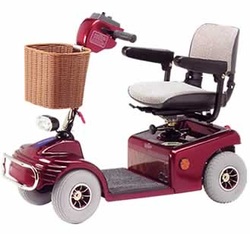
Ok so here goes another assault on the english language but thats just how i roll. Lets say your going to copy the videos and you want buy everything i did so at the bottom of this page there will be a picture of all parts used and if you click them you will be taken to a website where you can buy the exact same things which is cool i think. So first of all you will need a shoprider sovereign mobility scooter now these are very common so quick search on eBay will bring up loads of varying prices but hold out and you can pick them up for well under £100.
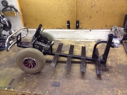
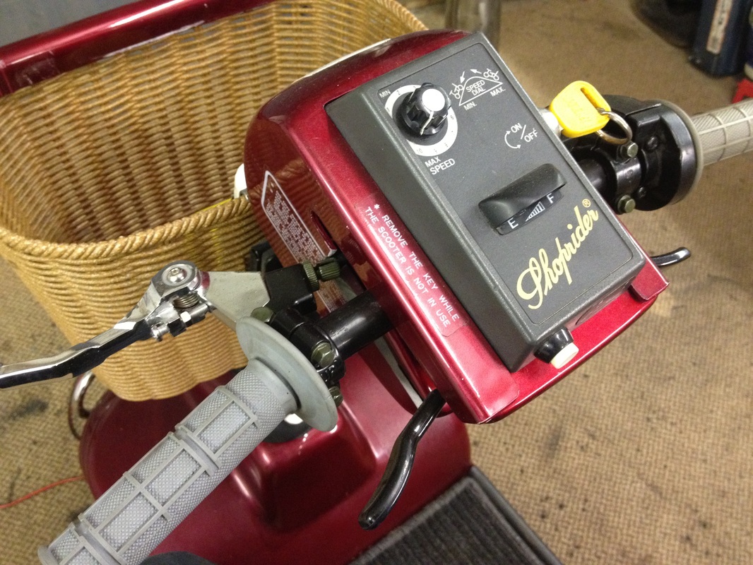
So first remove all the electric stuff you don't need that but keep the control panel with key and horn button as your going to want them later. Once all panels electrics are removed your left with the frame as pictured to the left here. You need to cut of the rear part with the seat post holder but cut it as close as possible to leave as much frame left as you can, again keep this piece you will need it again. Now to add your own bits of frame, get 2 lengths of box section (about a metre) and weld to the ends of the prong bits but you will have to cut same amount off so frame fits back under floor plastics as did previously. Now you have you adapted frame get you engine and figure out where you want it.
|
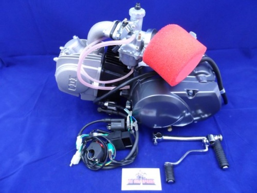
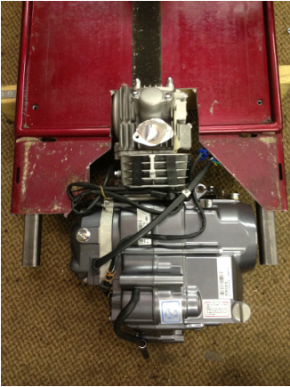
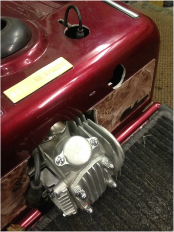
Ok the engines i use are pitbike engines these are great as you can have electric start semi auto manual and more powerful none electric start 140 and 160 versions, today im using a 125 electric start so we can turn key and fly + we will have battery so we can have the original light work. When finding you engine position you need to consider the axle, chain length, space four brake disc and how the lid will fit over it so.....The head will have to stick through the front of the lid unless you want the wheels completely out back of scooter or fancy doing some body mods. Also i found it best to sit engine as far right as possible to give more room for brake assembly and gear shifter, forget the kickstart it will end up behind wheel and well this is electric start so don't need it anyway. Your Axle wants to sit no more than 30-50 behind the engine, any closer will cause problems later which will be better described after second video. Once happy with location mark the floor plastic and trim.
|
|
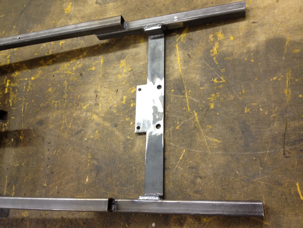
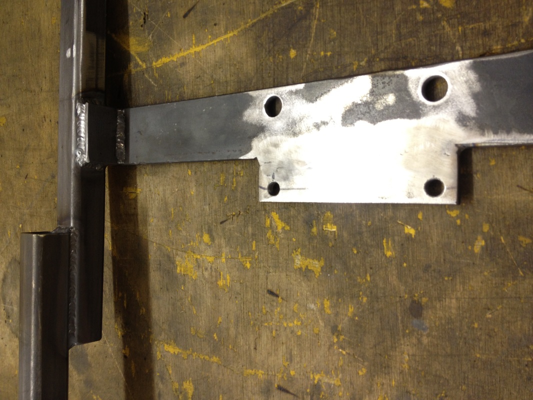
Now to add the engine mount and axle supports. To do this i add extra box section under the bit we added (you may want to cut them down if you welded super long bits on) i add this under to get the scooter sitting level if you didn't bother the scooter would either e super low and have ground clearance problems later or be high at the back and look a bit shit so do it this way. Its a good idea to have these pieces again longer than needed so they can be cut down to size afterwards. once you have welded these extra bits on you can support frame level and work out the bottom engine mount position and height, i found around 40mm is good any higher and you have problems later with engine cover and lower gives issues with gear shifter and waking ground all the time. There are 4 8mm threaded holes under engine which make the perfect fixing so a 6mm plate across is good enough but beware not to have plate go under the gear shifter shaft area as this needs to be kept freeish for later so i weld a piece on where the fixing holes are so the cross piece can be thinner, Theres lots of forward thinking at this stage but if you watch all 4 videos you will understand more what i,m saying (i hope). Ok thats enough for one video next up is the rear axle n brakes. see you soon CF
|
|
|
REAR AXLE TIME
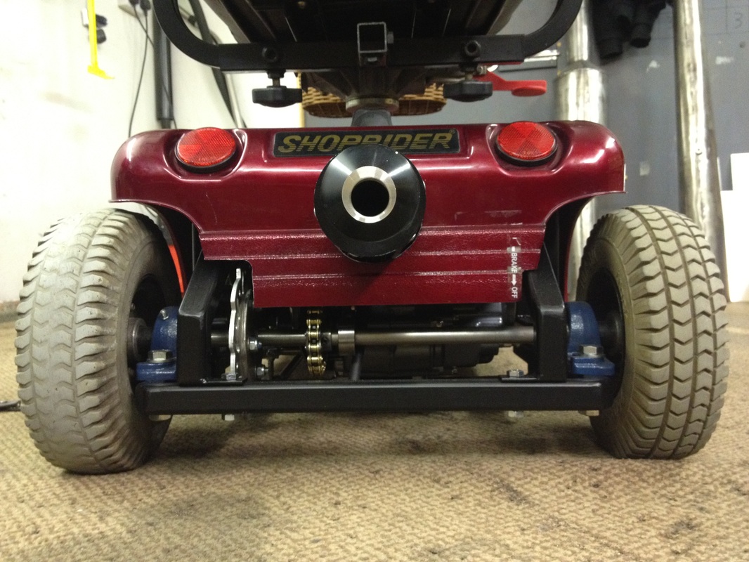
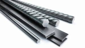
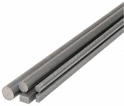
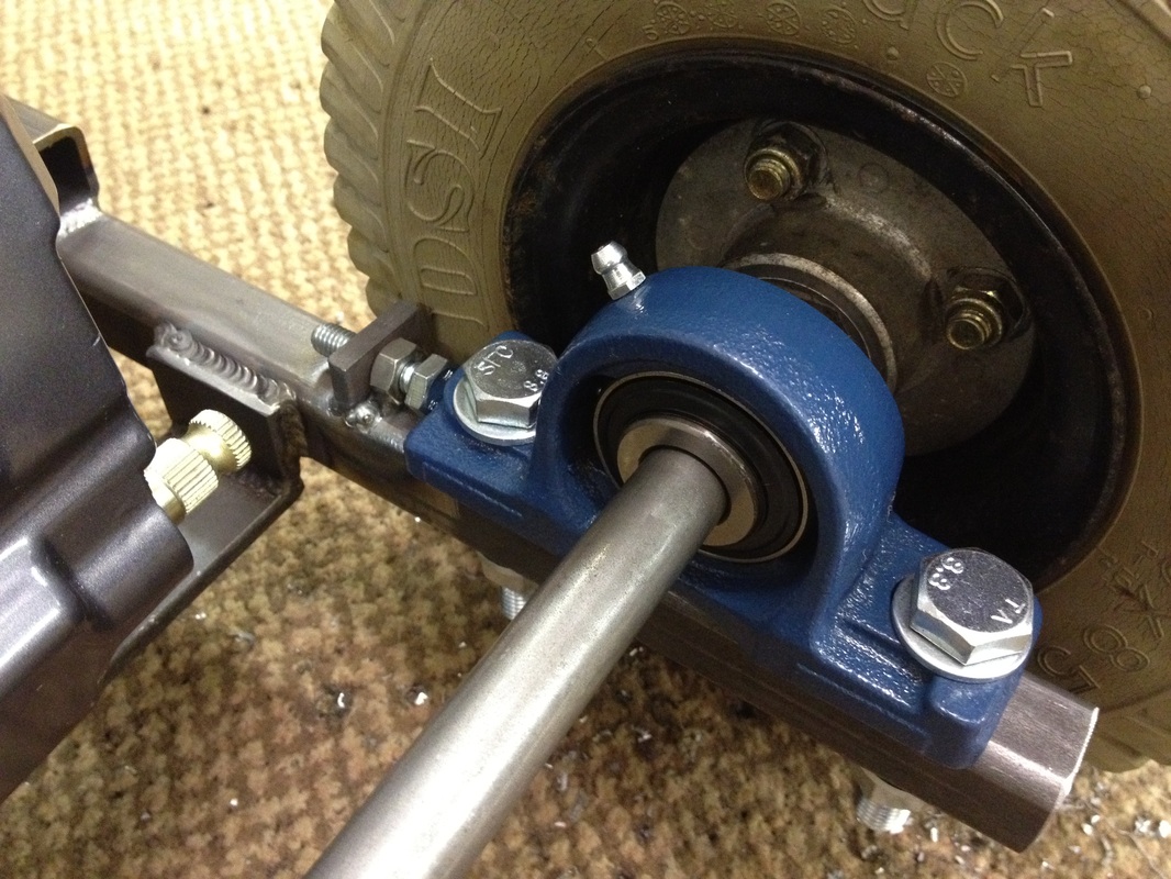
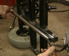
So we move on to the rear axle which is one of the reasons i put together this video series as i seemed to get a lot of questions on this part mainly due to the fact that i use the original wheels as like i said in the video it looks more authentic. You could use a go cart axle but its not going to to look as stealth as this thing does when its finished.Ok first job you need to get your 17mm BRIGHT STEEL bar if you get black steel which i don't think comes in 17mm anyway you wont get the bearings over it or it will be a bad fit. Bright steel is perfectly round and makes you think your good at making stuff when you slide the bearing over it and its a tight fit hehe. then put your 2 bearings over each end (links below remember) and offer up to frame to cut down to length. In theory for looks you want it to be as short as possible but don't have wheels to close to frame as they will rub on cornering ( about 10mm gap is enough) Once decided cut down to length. The wheels will stick out a bit as original frame never ran right through to end of chassis so the wheels motor set up was thinner, you could skew the frame in to reducer this wheel base but you will cause yourself problems later with space and also a wider wheel base at the rear does help with stability so i'd leave it.
|
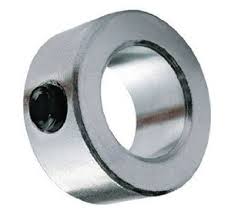
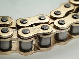
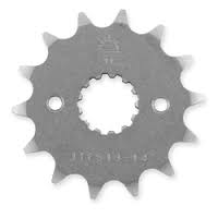
Next bit is to drill holes in frame to bolt the bearings down but before we can do this we need to make the rear sprocket so we can get some idea of the chain length and therefore know where the axle will sit. To make the rear sprocket you will need another front sprocket just like the one that will come on the engine and its very lucky that the shaft coming out of engine is 17mm so once you get rid of the teeth you have a 17mm hole in it "perfect". To remove teeth you will need a die grinding bit of some sort as this stuff is hard ,drills wont touch it so die grinding is the easiest option and cheap. On this scooter i'm running 14 teeth at front and 17 teeth at rear. Once teeth removed slide over axle then get a 17mm collar and but up against it.
|
|
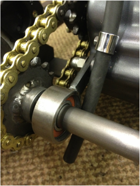
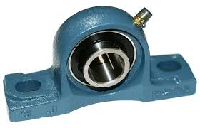
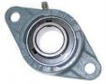
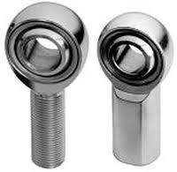
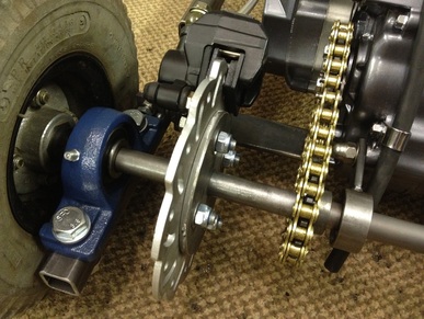
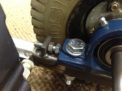
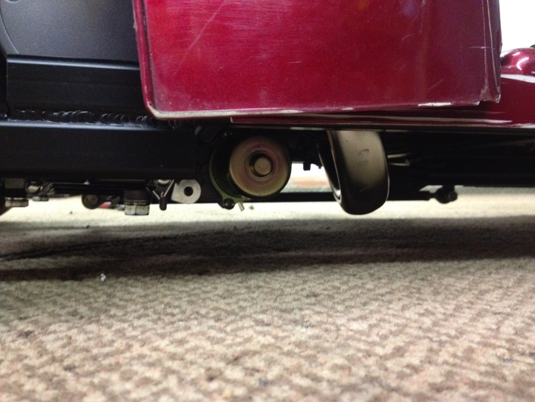
The point of this is to hold the sprocket at 90* to the axle before we fix it to it later and give a bit more stability. Just weld this to the sprocket then check for wobbles buy rolling on bench, to much side to side will wear your chain or at worst through it of, if you have any up and down (a result of die grinding an oval hole) this will cause your chain to have a tight spot but as long as isn't to extreme will be fine but best not have any really.now you can offer up axle on scooter cut the chain to length and mark holes were you need to bolt down the bearings, the axle wants to be around 40-50mm away from back of engine as there is a third bearing to consider. As we have a mild steel axle its not mega strong so it needs supporting so when you open up the throttle it turns the wheels and dosent pull the axle towards the engine. To stop this i mound a 3rd bearing on a post with slot in for chain adjustment which fixes to the engine on a mount which we will not use to hold the engine. If you don't have a lathe to machine out some tube for the bearing to sit in you can use one of these bearings (click here to see) this will work but you wont have any chain adjustment but it is an option.Now you can drill your holes and fix axle to frame, as a good tip its worth putting some tabs on frame with which you can slide some 8mm bolts through to act as chain tensioners (see pic above) ok its coming together now as with your wheels slid over axle you have a frame that moves again.

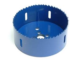
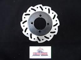
Ha now it moves we need to stop it, this is very easily forgotten as there was no separate braking system on original scooter as they have magnetic brake built into motor housing so theres nothing to remind you you need brakes. To start with get your disc and see how big the mounting plate needs to be (to big and caliper will foul on it, to small and fixing holes will be right near edge) i found a 98mm plate would be good and to make this you can get a 102mm Bi Metal hole saw and just cut it out some 6mm plate. I'm always surprised this works as i used to think these hole saws were for wood n plastics but i've gone through stainless with them so there great. now use the 6mm pilot hole in the centre to fix a washer the same diameter as the inside of brake disc so when you offer the disc up to mark the holes you have it central. mark holes and drill. your may need to grind top of bolt heads down a little depending on your caliper position. Now you have your plat fixed to your disc drill your pilot out to 17mm and repeat the process withe the collar like we did with the sprocket.
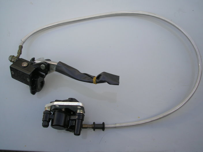
Put it on your axle then you can mount the caliper. the ones i use are front brakes for pitbikes but link is below anyhow. Mount the calpier in a position that you can get to the bleed of and the hose dose not foul the chain etc. The brake hose will not be long enough but you can get new ones made up buy a company called PIRTEK so once you now the lengths just ring em up or go see them, if your going to the Peterborough branch they can do it with there eyes closed now as have been in with many things. Mount the caliper with a plate to the frame where ever you think best.
Put it on your axle then you can mount the caliper. the ones i use are front brakes for pitbikes but link is below anyhow. Mount the calpier in a position that you can get to the bleed of and the hose dose not foul the chain etc. The brake hose will not be long enough but you can get new ones made up buy a company called PIRTEK so once you now the lengths just ring em up or go see them, if your going to the Peterborough branch they can do it with there eyes closed now as have been in with many things. Mount the caliper with a plate to the frame where ever you think best.
Now you have drive and brakes its just fixing the wheels to the axle so we need to cut some keyways. This is the only bit you may need to get someone else to do, i write these how to's with a person in mind that has basic a tool kit a cheap welder and thats about it hence why i offer alternatives when using a lathe for something. You can drill a few holes in a row and file the rest out but these need to be the best fit you can get or you will chew up the axle and the wheel hub with the woodruff key trying to twist. so saying that you have achieved this somehow then last of all drill n tap an 8mm thread in the end so you can stop wheel from sliding off. There will be a gap between the bearing and the hub which will needed to be filled and washers is the easiest way if no lathe available to make a spacer. Ok next job is setting the carb position and connecting the gears and systems up but thats a hole new video. next thursday chaps
Carb Electrics Gears
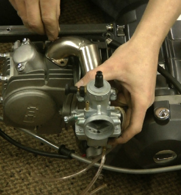
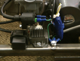
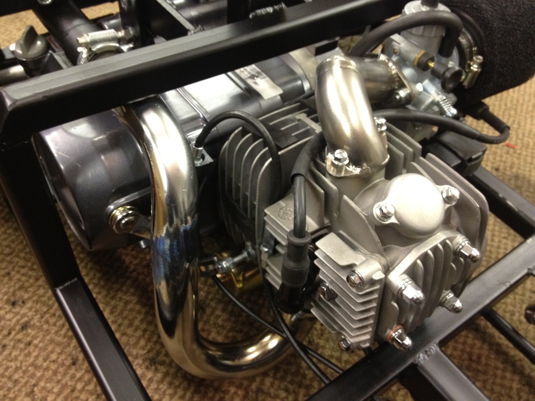
So now we move onto the smaller jobs.These are quiet time consuming and will cause swear words but once done your nearly finished First of is the carburetor now due to the minimal space above the engine and the fact that the seat post mount is just behind the inlet on the engine its easier to swing the carb round 90* and have it side facing which also helps with access to the choke once the cover is mounted. To do this you just need to find some suitable bends etc and then cut out your own plates using the gasket supplied with the engine as a template. I have on mine lowered the carb as well which means the outlet to the engine runs uphill but this hasn't effected performace.You could cut down and swivel the inlet pipe that is supplied with the engine but its ali and not many people have access to and ali welder Once this is done we move to the wiring loom.
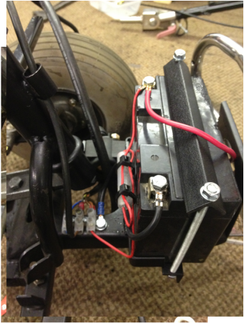
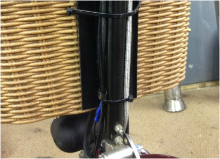
When you get your loom its not the right shape as such as its ment for a bike theres long bits short bits and bits that don't go anywhere. Unfortunately i can not give any info on which colour wires to cut keep etc because the looms aren't always the same color coding (pft Chinese) so all i can advise is strip back the plastic rap and resize stuff as you wish. I've taken all the earths and put them together myself as they look like they were put together on a friday. The one circuit you can separate is the starter circuit as all you need is a live to the starter solenoid ( the round thing with 2 10mm bolts on) and ive fitted this up at the front near the battery ( ive placed battery up front under cover just behind the bull bar) everything else is re covered and mounted just under carb inlet on frame although later i move the earth points when finishing of the frame so maybe leave that one for now. Another good idea is to run a tube under the frame, this will house the starter live cable the fuel hose and the engine live and stop cable. This is a great idea as there is little ground clearance it stops things getting snagged.
|
|
|
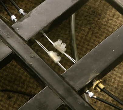
Now the throttle and clutch cables. As these are not a set length its best to do it in 2 half's and join them in the middle and the easiest way to do this is with electric cable junctions (yes they actually hold) to do this you will need to dill and weld nuts on to the cross members on the floor (these were part of the original frame) before drilling these its a good idea to put the exhaust on so you don't run the cables to close and melt them once running, try not to have tight bends or run the cable low to the ground as this will make for sticky clutch or catching the ground when running. The throttle cable on the top of carb will stick through the plastic cover so don,t try and hide this as you will kink cable. Fit adjusters each end to remove slack once clamped together. When ordering the engine order an extra throttle and clutch cable for other half's.
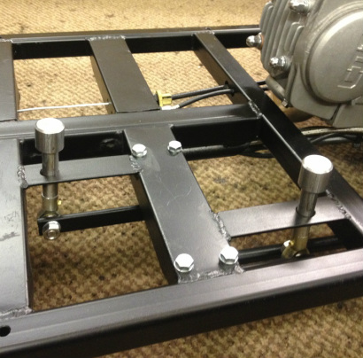
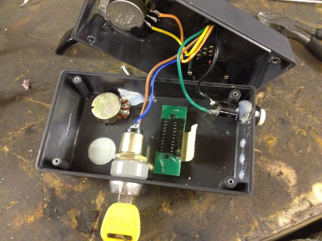
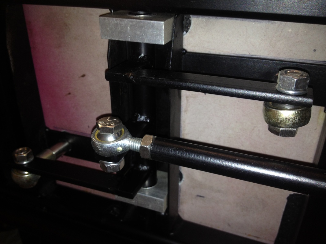
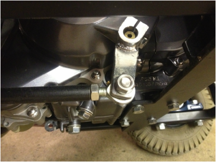
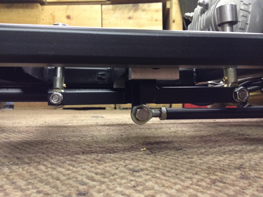
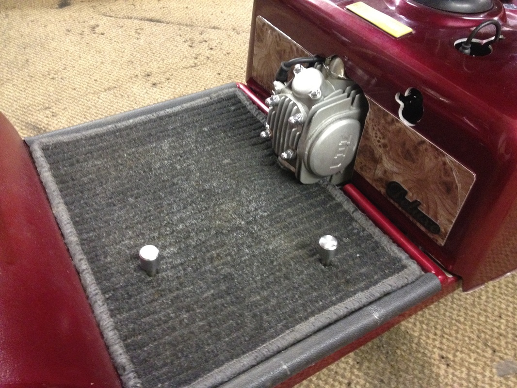
So just the gears left and proberly the coolest part.When people come up and talk to me when out with these machines they always seem suprised they have gears and are always think the 2 knobs that stick through the carpet is brilliant. There are many ways to do this as really your just doing the job of the gear lever further up the machine so if you think a gear lever is around 4" long then as long as you have about 4" of leverage from your pivot point the resr is just matching the movement. First of cut down your gear lever and drill an 8mm hole for rose bearing to attach to, the lenght you cut it down to is up to you, the longer the better but this is most likely going to be the lowest piont of the machine so if you can keep it shorter do it. I cut mind down to around 2" and had it pointing just about stright down. Then underneth the floor you need to set up a lever system that matches what the gear lever would do so in my case have a bit that sticks down 2" and arms that extend 4" then it all works as a normal gear lever would. If you go shorter than 4" the gears might be hard to engage or put to much force on the links and go to long and you will have alot of travel. Now as its difficult to understand my bad english ive taken lots of pictures for you to copy from, BRILLIANT
|
|
|
|
AND ITS FINISHED
Woo Hoo its nearly finished. So last jobs to do is the exhaust and remainder of the frame but before you attempt these its a good idea to cut the plastic engine cover left over from original scooter as this will tell you how much room you have managed to save and what height you can go with your frame and last but the most important the position of the seat post. Once cut out around engine remember to have spark plug cap in at this point so you don,t forget to allow for that and also access to the choke, its also a good idea to cut a slot for the throttle cable to pop through rather than having tight bend on top of the carb. once all this is cut mark the centre point of the hole where the seat post will come through then you can start work on the rest of the frame. Its also good to make a note of the height of frame to under side of cover at the places you wish to have your frame mount points so your not putting on and off the cover repeatedly.
|
|
|
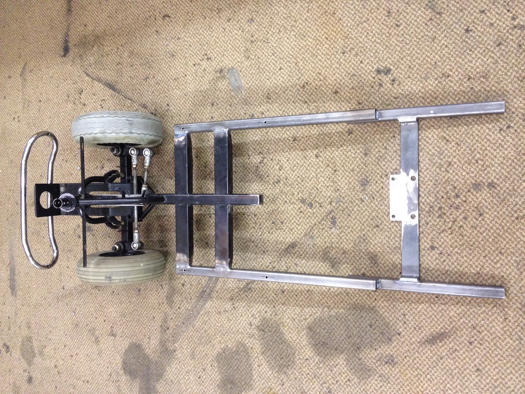
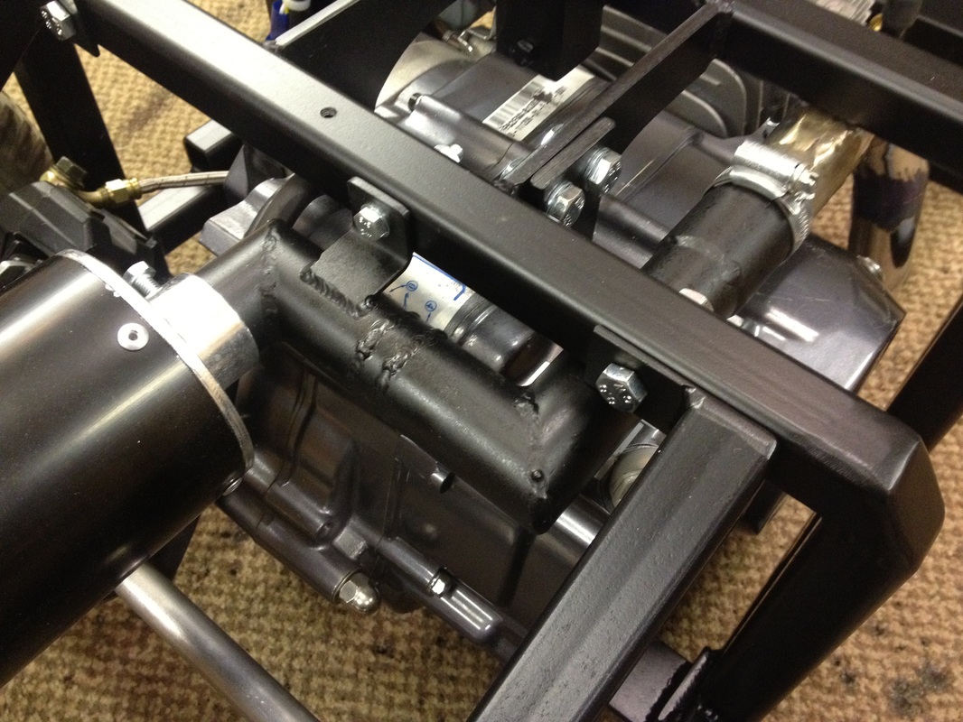
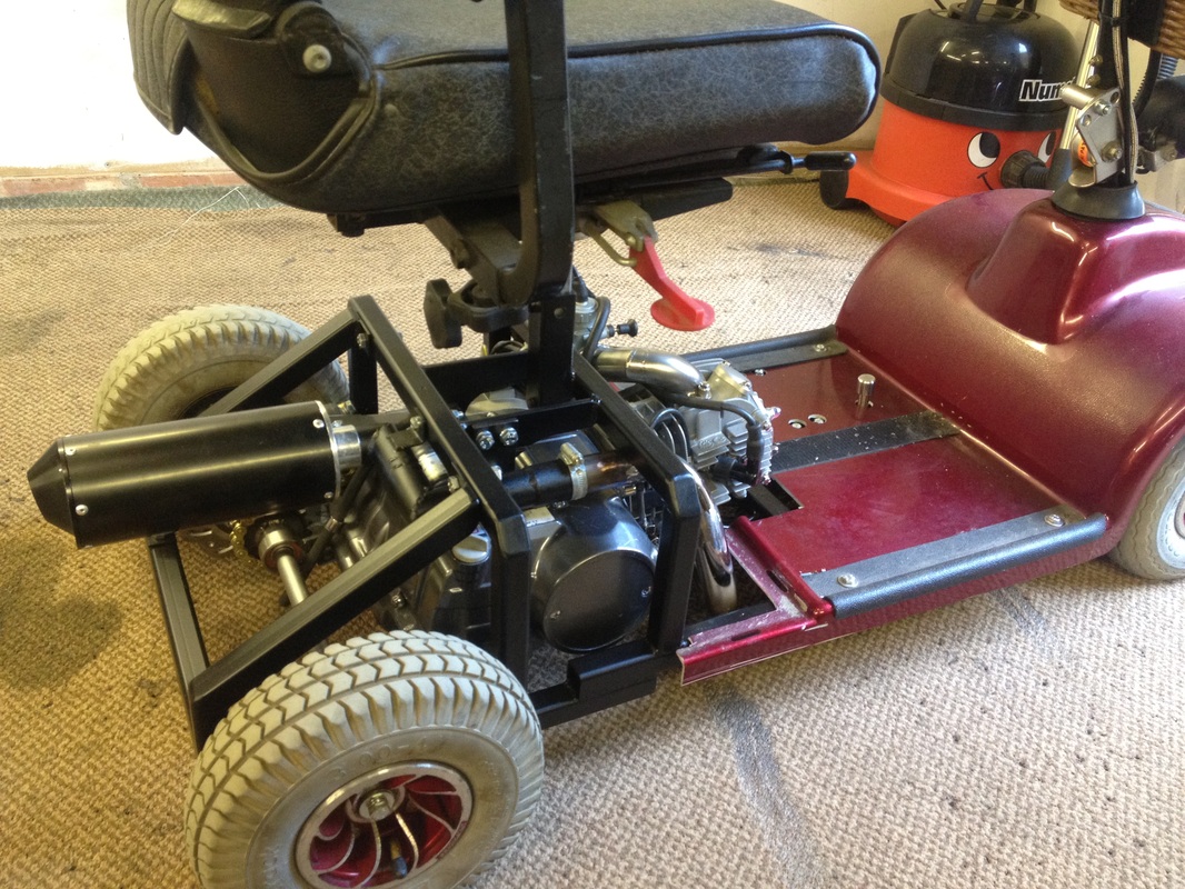
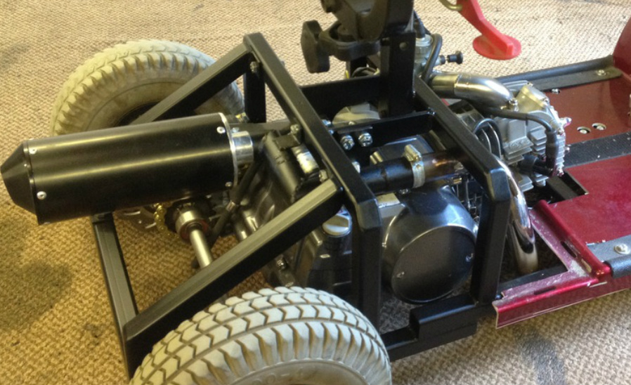
Now the next part sort of needs you to do 2 jobs at once or at least think of them both as the frame will have a big effect on the exhaust and like wise so you need to plan your exhaust route before you start your frame. I found the exhaust will fit under the frame but will need splitting in 2 sections as you can not bend it through when its in its final shape, other thing to note is not to cover engine oil filler. I found the exhaust has to be reshaped quite a bit so i cut after each bend so could adjust angle then re welded them up. Once you have a mental picture of exhaust route you can build the remainder of the frame i put 2 straight pillars up with bars joining them and welded the seat post to one of them. I looked at using a fresh bit of box for seat but as i said in the video its a queer size and hopefully you have saved it. I then used the brace between the struts to mount the top engine mount to but be careful not to BOX the engine in as its very easy to forget you might/will have to take engine out to paint frame or maintenance etc so imagine the engine sliding forwards or backwards and look to see if any of the budges on the engine will foul your mount, i found my right hand side plate needed a bolt of part to help with this. Once this is done to add a bit of strength i also added some diagonal supports which also can be unbolted so rear axle can be removed. So now with your frame finished its ready to finish exhaust and like the new F1 cars i opted for straight out middle which ment putting some bends in which some people will say is bad for flow but its not going to make much difference to this. So with all that done you can cut extra hole for exhaust in cover put on and boom your nearly there its just a fuel tank away. The fuel pipe was routed with the starter cable through that magic tube we welded underneath so is dangling around at the front. post this up the the floor and mount your tank in the basket. You could use a fuel tank of anything really or like i did buy a bottle dill hole in the bottom and fit fuel tap.
AND ITS DONE
So you have done all the work now just to pull it to bits, paint and take for a spin. The top speed i,ve manged on this set up of 14-17 sproket set up on rear and electric start 125cc engine is 58mph. Ive also previoursly built one with a 14-18 gear set up and 140cc push start set up which maxes out at 55mph but has no slow gears it just pulls in every gear, this one is a little slowish in 3rd and 4th but still great in 1st and 2nd. The electric start is great and also because you have a battery you can rig up the lights to work for a proper stealth look. Well enjoy your super scooter and hope this has helped in some way. COLIN FURZE

|
|
|
|